Surgical Technique for ZMS Recon Nail
Nailing Procedure
Step 4- Proximal Locking
Use the Recon Proximal Targeting Guide for retrograde insertion of thetwo screws through the nail and into the femoral neck and head. Correctrotation of the nail is imperative for insertion of the retrograde screws.Be certain that the nail is inserted to the correct depth to allow placementof both screws with the correct anteversion.
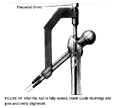
Insert the three nested Guide Bushings through the distal hole of theProximal Guide to the level of the skin. Make an incision in the skin andfascia at this point and continue to insert the Bushings until contact ismade with the lateral femoral cortex. Drill a 12-inch Steinmann Pin throughthe inner Bushing and into the bone. Verify the proper position of the pinwith an AP image. At this point, the surgeon may drive the nail in or outto ensure proper alignment of the guide pin through the nail and into thefemoral neck.
Verify the proper position and anteversion of the pin with APand lateral C-arm views.
The Recon Proximal Targeting Guide is radiolucent so it will not blockthe lateral view. If the position is not correct, remove the pin and adjustthe nail rotation~and/or nail depth. Then verify the new pin placement withthe C-arm.
 Now place the secondset of three nested Guide Bushings into the superior hole of the ProximalGuide. Drill the second 12-inch Steinmann pin in and verify its positionwith the C-arm (click image to enlarge). If the position is unacceptable,remove both Steinmann pins and reposition the nail. If correct positioningis obtained, remove the Threaded Driver or Slaphammer prior to removingboth Steinmann pins and 3.2 mm Guide Pin Bushings. Insert the 5.0 mm CalibratedDepth Gauge Drill into the 5.0 mm Drill Guide Bushing.
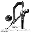
Drill the distal proximal screw hole while monitoring image intensificationto prevent penetration of the femoral head (click image to enlarge).Read the proper screw length directly from the Calibrated Drill (SeeFigure Inset). Remove the 5.0 mm Drill and Drill Guide Bushing.
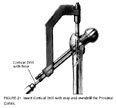
Insert the 6.5 mm Cortical Drill with Stop through the outer InstrumentGuide Bushing and overdrill the proximal cortex (click image to enlarge).Remove the 6.5 mm Drill.
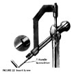
Insert the appropriate length 6.5 mm partially threaded cancellous screwthrough the outer Bushing using the T-Handle Screwdriver to the correcthash mark (click image to enlarge). Visualize seating of the lockingscrew to ensure proper seating well within the femoral head.
The first screw should lie on the medial cortex of the neck to allowroom for the second screw to be placed. This may be difficult in small patientsor patients with varus hips. Take care to get the inferior screw tightlyagainst the medial cortex to prevent varus deformity and to allow for insertionof the proximal screw.

Remove the Screwdriver and Instrument Guide Bushing. Take AP and lateralC-arm views to check for correct positioning. Repeat the same proceduresfor insertion of the most proximal locking screw (click image to enlarge).Again, observe AP and lateral C-arm views to ensure proper seating withinthe femoral head and neck.
Remove the Large Locking Bolt and Recon Proximal Targeting Guide.


