
Use the plastic Exchange Tube to remove the Bulbtipped Guide Wire andinsert the Smooth Guide Wire (click image to enlarge).
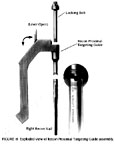 Attach the selectednail to the Recon Proximal Targeting Guide*. To be sure you have selectedthe proper nail style and Proximal Guide, identify the three grooves onthe Targeting Guide and the three grooves on the proximal end of the nail(See Figure Inset - click image to enlarge). With the ratchet leverof the Proximal Guide in the open position, insert the Large Locking Boltthrough the barrel of the Guide . (To open the lever, apply slight tractionstraight out and then flip lever up.) Close the ratchet lever and use theT-Handle Screwdriver or Pin Wrench to tighten the Large Locking Bolt intothe proximal end of the nail. The ratchet mechanism in the Guide will preventthe Large Locking Bolt from loosening during insertion of the nail.
NOTE: If the ratchet mechanism of the ZMS Recon Proximal TargetingGuide does not operate freely, it may be necessary to disassemble, cleanand reassemble. If the ratchet mechanism becomes inoperative it may be removed.The assembly will still function; however, the Locking Bolt may loosen duringthe procedure.
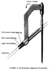
Proper alignment must be verified before each use. To verify, insertthe 3.2 mm Guide Pin Bushing into the 5.0 mm Drill Guide Bushing; then,insert these two nested Bushings into the 8.0 mm Instrument Guide Bushing.Place the three nested Guide Bushings through one of the holes in the ProximalGuide. Insert the 3.2 mm, 12-inch Steinmann pin through the inner Bushing.When the device is properly aligned, the Steinmann pin will pass throughthe hole without contacting the nail. Repeat this procedure for the otherproximal hole (click image to enlarge). After ensuring proper alignment,remove the pins and Bushings.
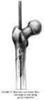
Place the selected nail over the Smooth Guide Wire and into the femur.Screw the Threaded Driver or Slaphammer onto the back end of the LockingBolt. Begin seating the nail using gentle impaction (click image toenlarge). While impacting the nail, use the Proximal Guide to maintainthe proper rotation.
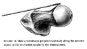 To determine the correctanteversion, slide a 12-inch Steinmann pin percutaneously along the anterioraspect of the trochanter parallel to the femoral neck. Verify pin placementwith the C-arm (click image to enlarge)). This will help to identifythe anteversion of the neck. During insertion, the Proximal Guide must remainparallel to this pin to ensure proper anteversion for the locking screws.
Continue careful insertion of the ZMS Recon Nail. Visualize the fracturein two planes with image intensification to ensure proper passage of thenail into the distal fragment. As the proximal end of the nail approachesthe greater trochanter, reduce the force of impaction. If excessive resistanceis encountered during nail driving, the nail must be removed and sizingof both the reamer and nail should be checked. Once proper sizing has beenconfirmed, the surgeon may choose to overream the canal further or selecta smaller size nail.
Continue to seat the nail until it is flush with the trochanter. REMOVETHE GUIDE WIRE.
![]()
![]()
![]()